


I built mind-controlled ears as a way to learn how to build my own arduino-based designs. Challenges included cable management and designing custom servo hardware to attach to the asymmetrical EEG headset.
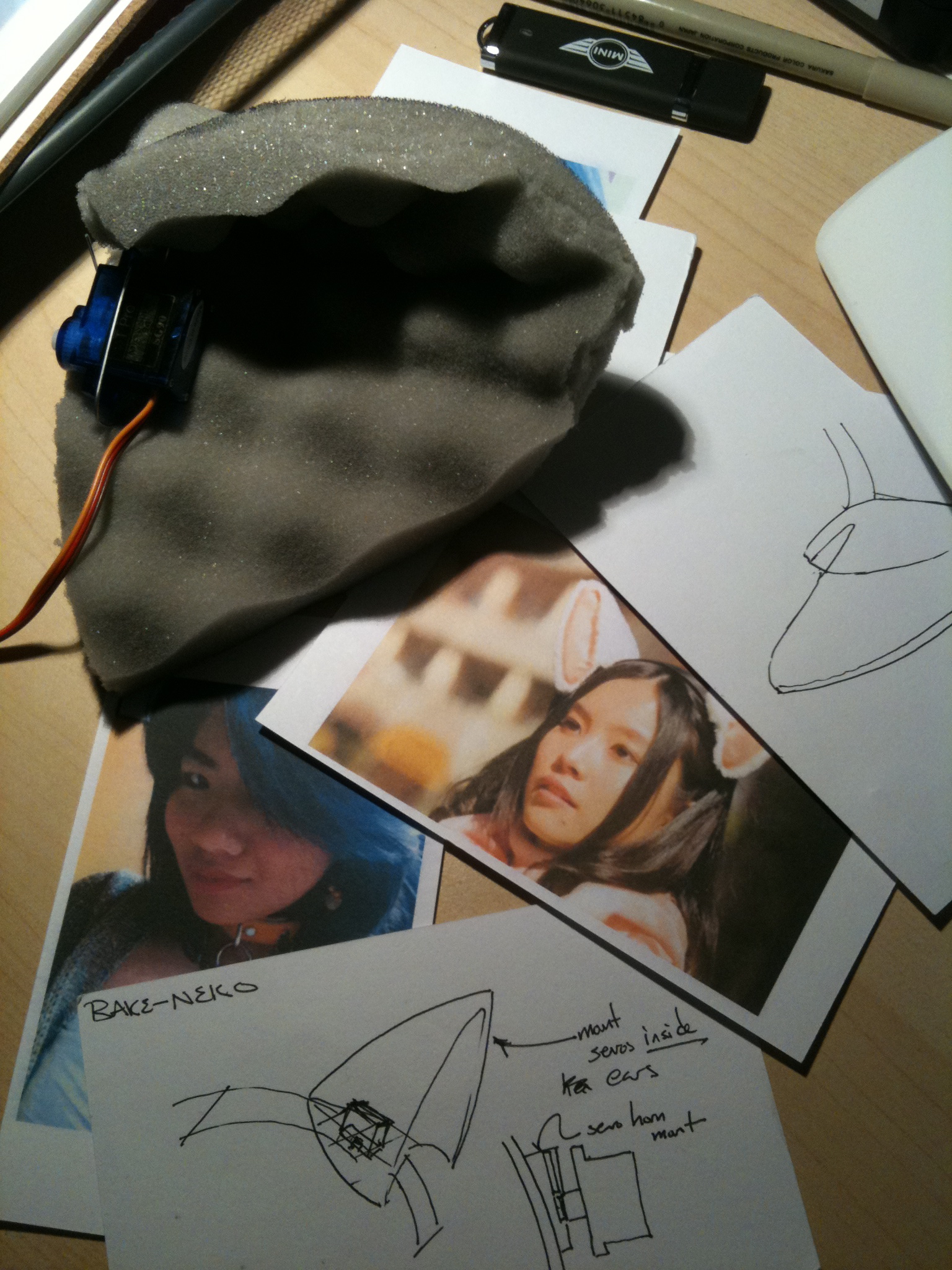
I began by looking at the youtube concept video for the necomimi brainwave-controlled ears. My intent wasn't to copy their implementation, but I was curious what kind of motion they had decided on.
The video seemed to show ears moving on a single axis of rotation, pivoting at the base of the ear. This choice makes sense for a mass-produced headset. You want to minimize elements in the BOM, and also each motor you add is a potential point of failure.
I made a couple of motorized sketches with a single rotation axis (below), but didn't like how the movement looked.
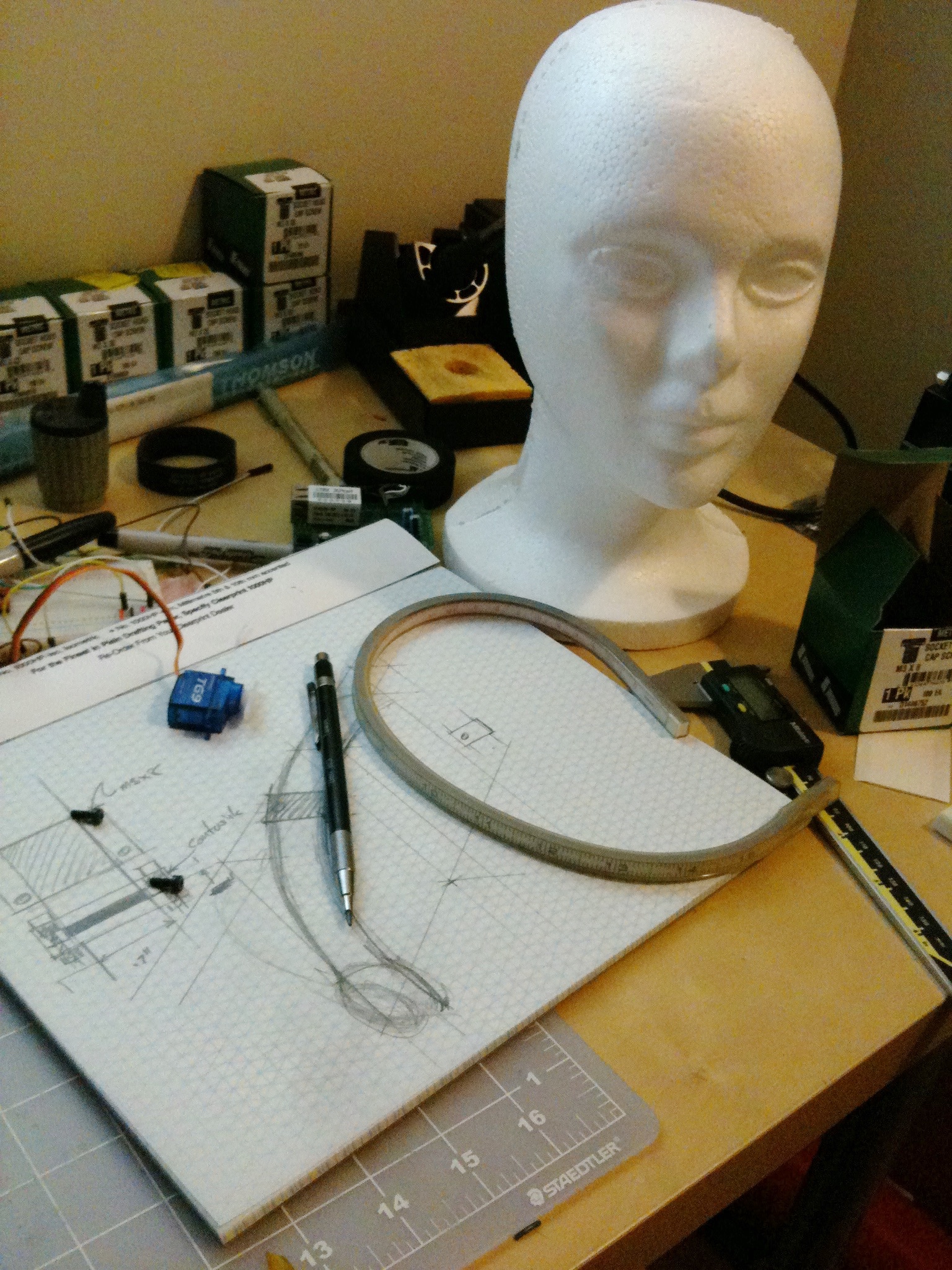
Regardless of how I constructed the ears themselves, one thing was clear: I had to mount servos to the MindWave headset band.
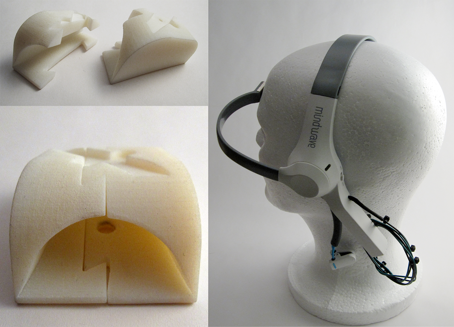
The first step was to measure and sketch out the band, then model it in Solidworks, so that I could design 3D-printable hardware to fit around it.
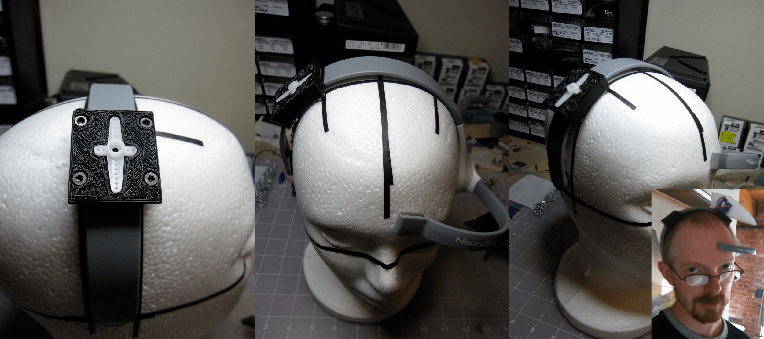
The servo mounts were modeled in Solidworks, printed using my MakerBot Cupcake 3D printer. The MakerBot's printing capabilities were very rough, and imposed significant constraints on what I could design and easily print.
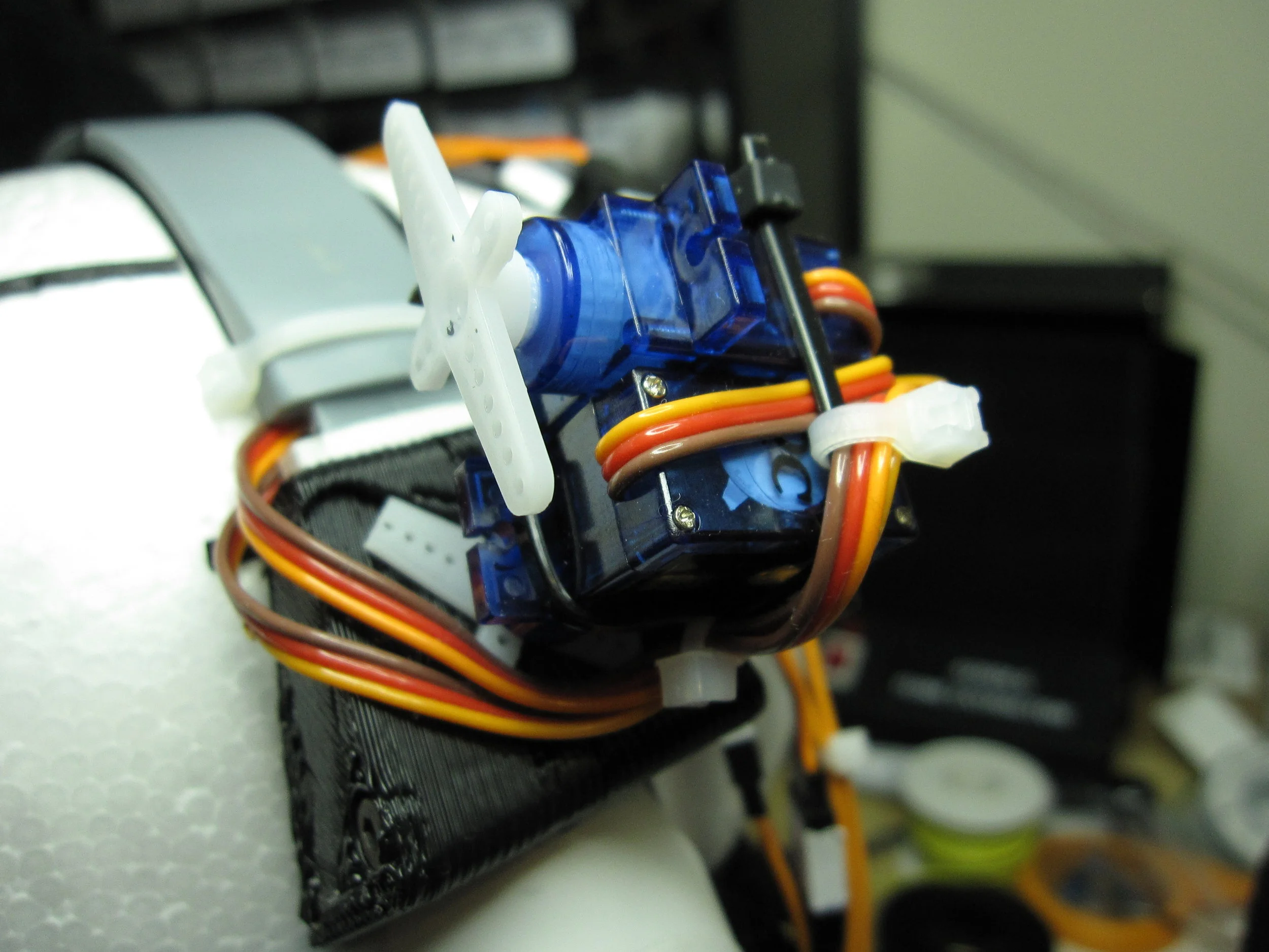
The servo's "horn" fit more-or-less precisely into the recess on the mount, and a screw (inserted from underneath) would attach the servo to the horn, and pin the horn to the mount.
The servo mounts gave me one axis of rotation. I experimented a bit with different ways of connecting servos together, and settled on a pan and tilt orientation. The video below shows the servos being controlled by an Arduino, running a motion test.
My concern was coming up with hardware that could be used expressively for ear animation.
In order to design the animation of the ears, I needed ears.
One experiment was to use a wire armature (shown below) and use fabric stretched over it.
The other option for ears was a 3D printed shell, with a fabric over-layer. This gave some control over shape, without getting into soldering wire frames together.
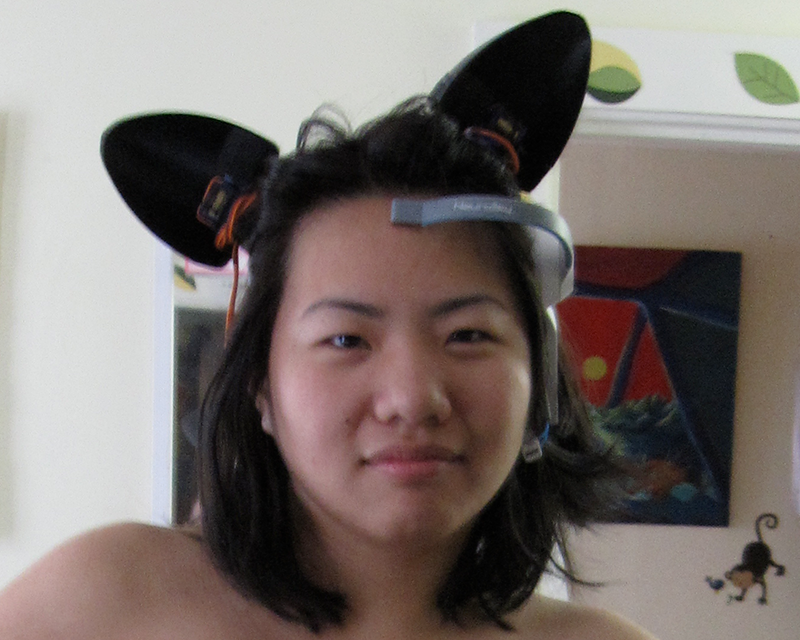
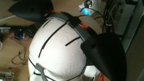
I assembled the ears and tested their fit on me, but when Amber put them on, I realized that I hadn't taken relative head shape and hair volume into account. The fitting photo below shows the result.
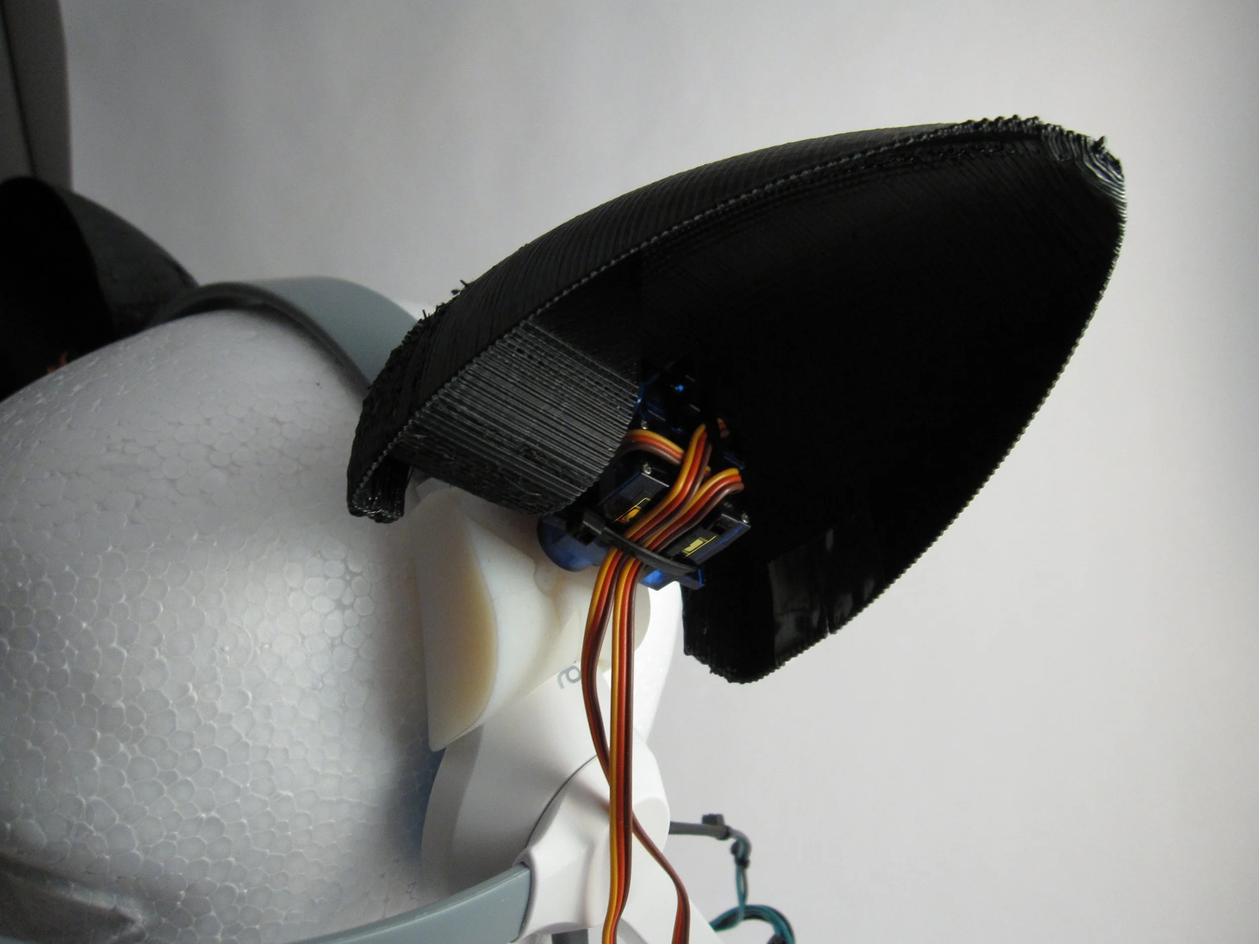
In order to fix this problem, I would have to drastically re-design the servo mount on the side of the headset with the EEG hardware.
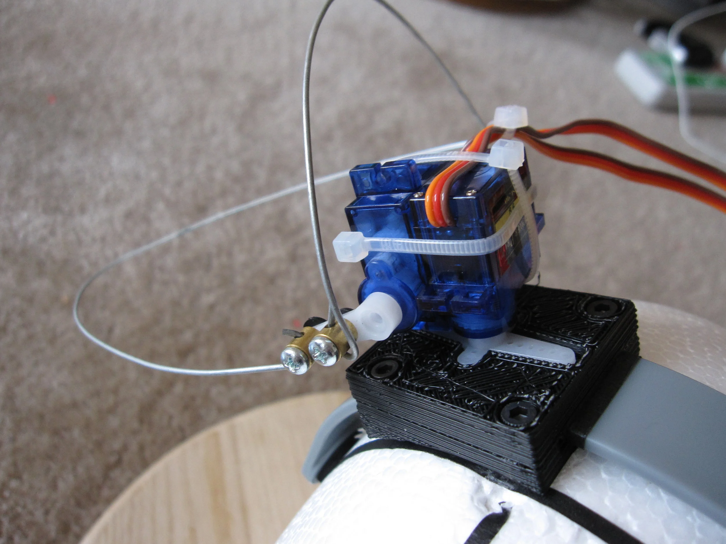
In order to get the ears to fit Amber's head correctly, I had to mount the left servo over the organic bulge of the white part of the headset (below right).
I measured and modeled that part of the headset, and designed a servo horn that would fit perfectly, and slotted together like puzzle pieces (below left).
(The light tan colored hardware shown directly below was printed on a commercial 3D printer later. The actual hardware I used for the project is the rougher, black ABS plastic in the photos below it.)
Once I had the ears mounted, it was time to design the animation. In order to do that, I first had to simulate the input from the MindWave headset, since that is what would control the animation in production.
The MindWave EEG headset sends a number of variables via serial: a value for each brainwave type (alpha, beta, gamma, etc.), and two "interpreted" variables, which are composited from the raw brainwave measurements by the TGAM chip embedded in the headset.
These values are "Attention", and "Meditation". Each is an integer value from 0 to 100.
Attention is a measure of focus. The more you concentrate, the higher the variable.
Meditation is a measure of mental relaxation. Calm your mind, and the variable value increases.
The two variables work together: it is possible to have a very high attention along with a high meditation value.
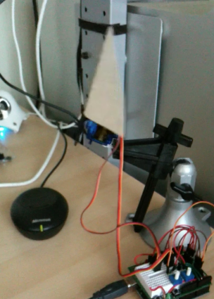
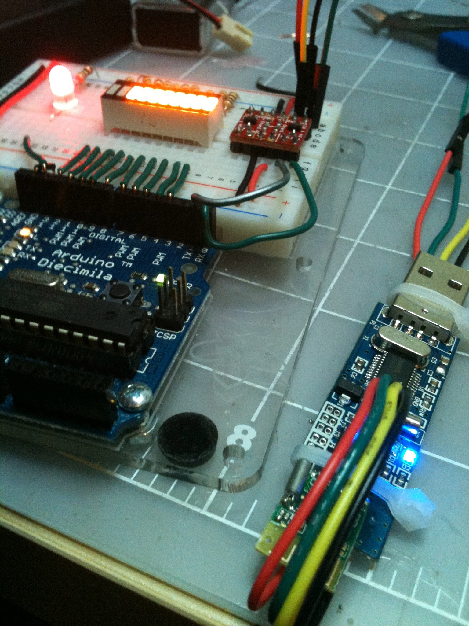
For the purposes of this experimental project, I chose to focus on animating the ears based on attention. So I put together a breadboard circuit (shown below) with a potentiometer attached to the Arduino's analog input, which returned a variable ranging from 0 to 1023. I used the map() function to scale that from 1 to 100, and stored that as my attention variable.
So, by turning the knob on my breadboard, I could simulate the input from a MindWave EEG headset, and start writing code to animate the movement of the ears based on that input.
Below is a video showing one of the animation patterns in a loop.
The Arduino is sweeping the attention variable from 0 to 100, pausing, then sweeping down to 0, pausing, and repeating the loop.
The design intent was that, if the wearer's concentration lapsed, the ears would droop to the sides, like a sad anime cat. When the wearer focused, the ears would stand to attention.
There were many, many adjustments of the motion of the two servos together to get the animation to look as natural as possible.
The next step was to actually connect the MindWave EEG headset to the Arduino and control it, rather than simulating the attention variable.
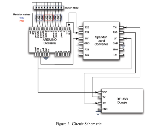
At the time, the MindWave headset used a USB radio dongle to talk to a computer, which could be modified to speak to an Arduino. The process was complicated by the fact that the dongle used 3.3V logic, and Arduinos at the time were all 5V. So specialized hardware had to be used to level-shift the data signals and provide the dongle with the proper 3.3V on its power line.
(Note: if you buy a MindWave headset now, it uses Bluetooth to talk to a computer, and pairing and accessing that with an Arduino is essentially trivial. But this was 2011, and I was not so lucky.)
Above, the schematic provided for connecting the MindWave to an Arduino.
Success!
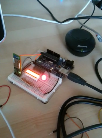
Shown above, and in the video below, is the Arduino receiving EEG data from the MindWave headset through the RF USB dongle.
The breadboard has an LED bar, which lights up according to how intensely the wearer focuses their attention.
The video shows the result of me wearing the headset and making the LED bar go up and down, and the EEG and attention and meditation variables streaming to the computer via serial monitor.
The next step was to put everything together.
I combined the animation test rig and the MindWave rig. Since I had been testing the animation from the start by interpreting an attention variable, it was nearly trivial to combine the two Arduino sketches. I just replaced the AnalogRead() function with the already functional MindWave code.
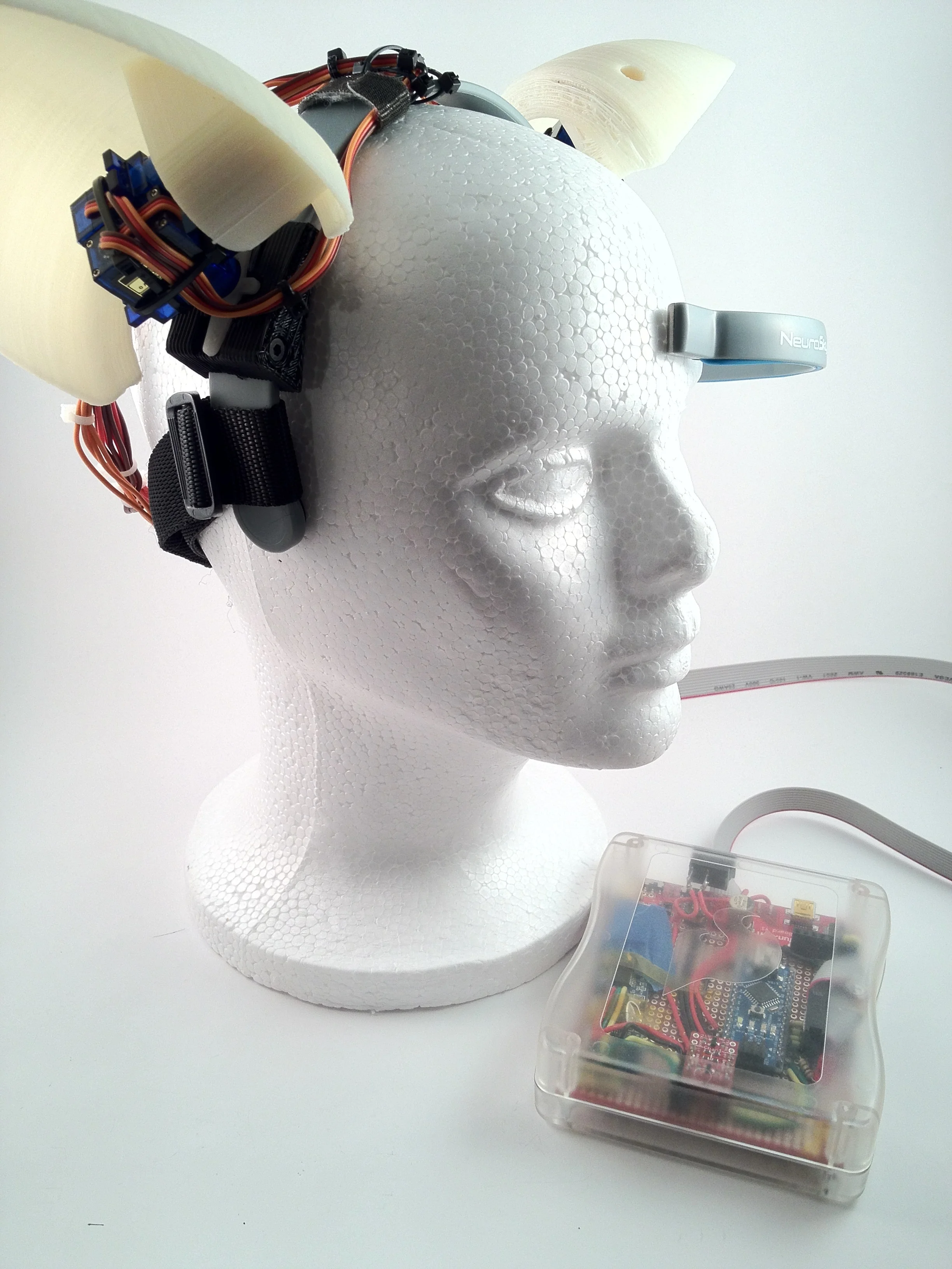
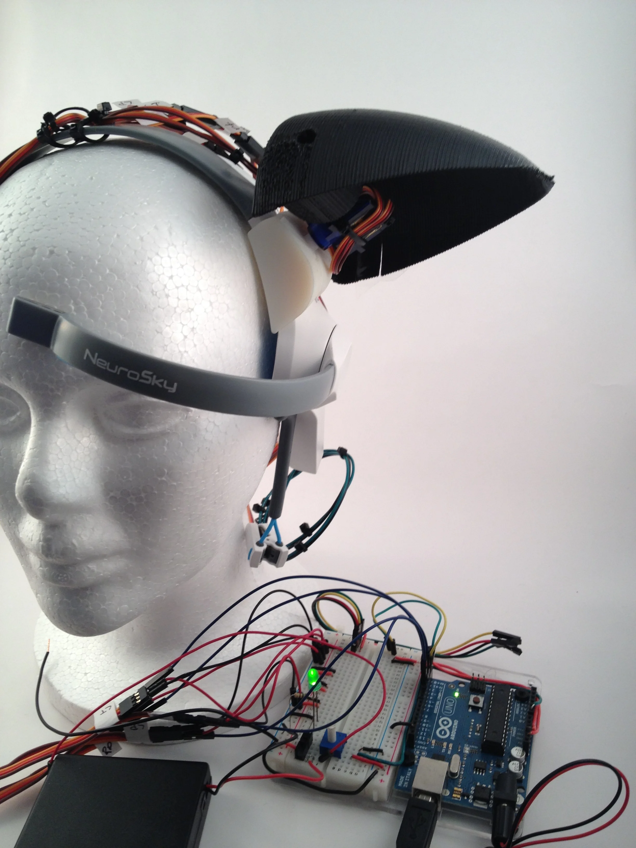
Result: a mind-controlled headset.
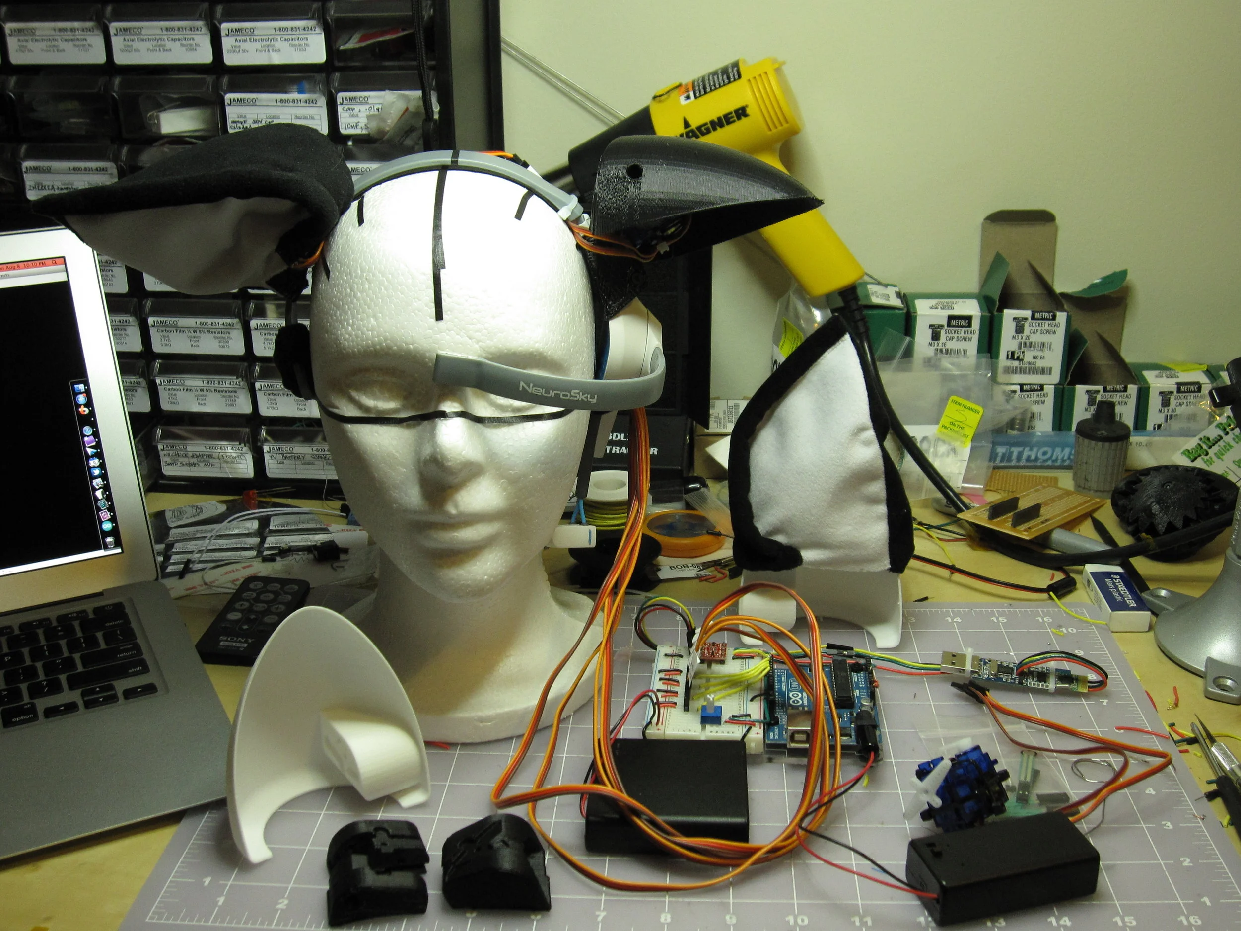
Above: the fully-functional EEG animation test rig on the workbench.
(Also shown is the fabric ear covers, sewn for me by my generous friend Miriam Byroade.)
Below: video of the first time controlling the ears with a MindWave headset (which is off camera, of course). It was difficult to keep the camera steady because I was a bit excited.
Below: Fine tuning the animation with the fabric covers on, and learning to control the ears with the headset.
The next step was to take the bundle of crazy servo wires, breadboards, battery packs, RF dongle, and bulky Arduino Duemilanove, and turn it into something a real human could carry on their body.
One complication was the RF USB dongle, which required a 3.3V power supply, while the Arduino would want 5V. Another was that the servos for the ears required their own battery, as the Arduino was incapable of powering all four of them reliably.
My first attempt used a pair of AA batteries as a naïve 3.3 volt power supply for the RF dongle, and a bundle of AA batteries for the servos mounted on a wearable collar. This resulted in a functional wearable design that fit into a fabric bag. (Shown below.)
Unfortunately, the unregulated power from the AA batteries would occasionally cause the RF dongle to reboot and send a burst of garbage data to the Arduino, which would then crash and reboot.
This first prototype fit well on Amber's head, and we wore it out into Boston to give it a test run.
The animation of the ears worked well and was easy enough to control for Amber, although not being able to see them on her own head made it more difficult.
Below, you can see the extreme interest animation: I wrote the animation code so that, if the wearer's attention variable suddenly increased to over a certain threshold, the ears would execute one of a few randomized "wiggle" animations.
This was triggered by Amber looking at the menu of the coffee shop we were in and trying to decide what to order.
The first prototype taught me many things.
• I needed a regulated power supply for the dongle.
• AA batteries worked, but were super bulky and didn't last long
• The weight of the ears made the headset move around on the head.
• Do not make your control pack to be worn under a skirt.
The last lesson was learned when the RF dongle's power wire came loose in the middle of downtown Boston, and we ended up in the corner of a Dunkin Donuts, with me casually reaching up the side of Amber's skirt, attempting to reconnect the loose wire by feel. Wearables can be awkward, y'all.
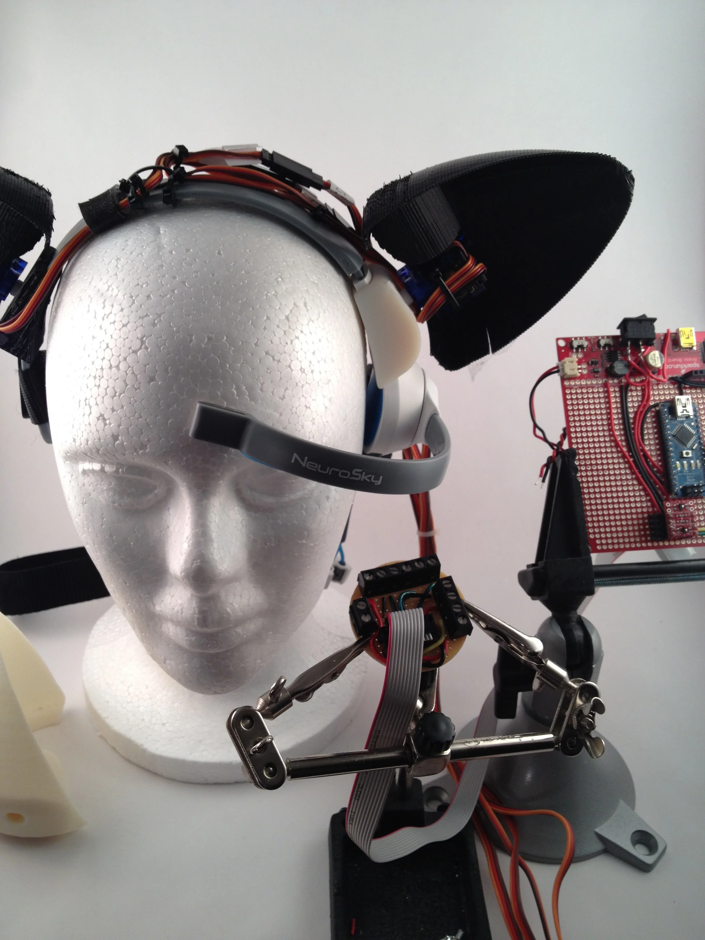
The final prototype used an Arduino Nano and a Sparkfun prototype board, with lithium polymer rechargeable batteries to power the Arduino and the servos. The Sparkfun board had built-in power regulators, which provided both 5 and 3.3 volts, and a common ground.
It would have been nice to miniaturize the whole thing further so that a separate cable and control box wasn't necessary.
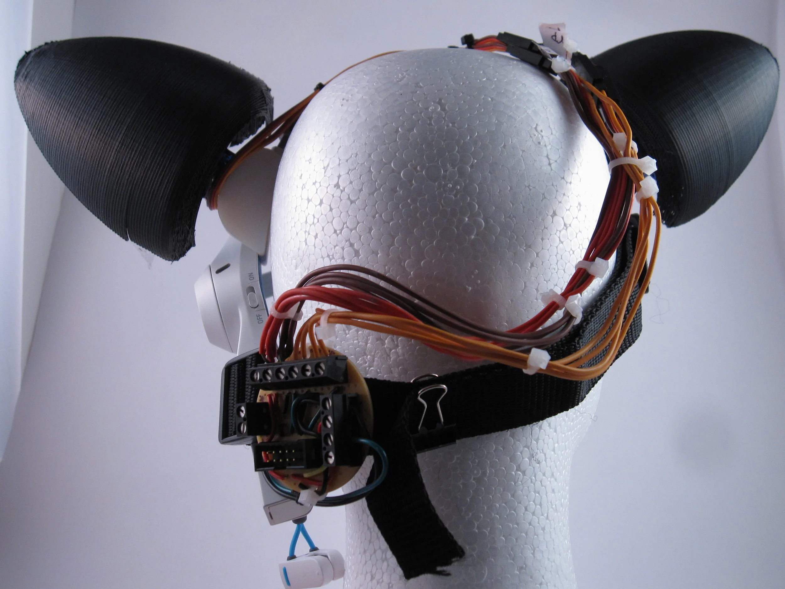
The second (and so far final) prototype used lithium polymer batteries in the Sparkfun enclosure, and a ribbon cable carried power and servo control signals to the headset, plugging into a terminal board (shown below).
Also shown below is a fabric strap added to the design, which would keep the EEG headset's probe attached to the "magic spot" on the wearer's forehead.
I took this project on, not because I knew how to do it, but because I did not.
The purpose of the experiment was to take the beginner Arduino and electronics skills I had been teaching myself, and push their boundaries in order to produce a rough functional prototype. And also to make a friend happy by letting her wear robotic cat ears.
I learned many lessons in the process, not least of which was how critical and complicated cable management could be, and how that affects and dictates the design of enclosures and other hardware.
By far my weakest skill at the time was my ability to write code for the Arduino microcontroller. At key points in the development process, my friend Jeff Cutler contributed his skills, and I could not have completed the animation code without his help.
At the end of the project, there was much progress that could still be made. But I had met my goal by constructing functional mind-controlled cat ears with relatively sophisticated animation. I released the files on Thingiverse, and the code on GitHub.
The project ended up gathering a bit of attention at the time. MakerBot employees got in touch, and interviewed me for the company blog. And when they heard that I had printed the hardware on a Cupcake, they printed better versions of it on a then-secret MakerBot Replicator and mailed it to me. Cooooooollll.
In the end, even though there are so, so many things about the ears I would do differently today, I am proud of the accomplishment.