
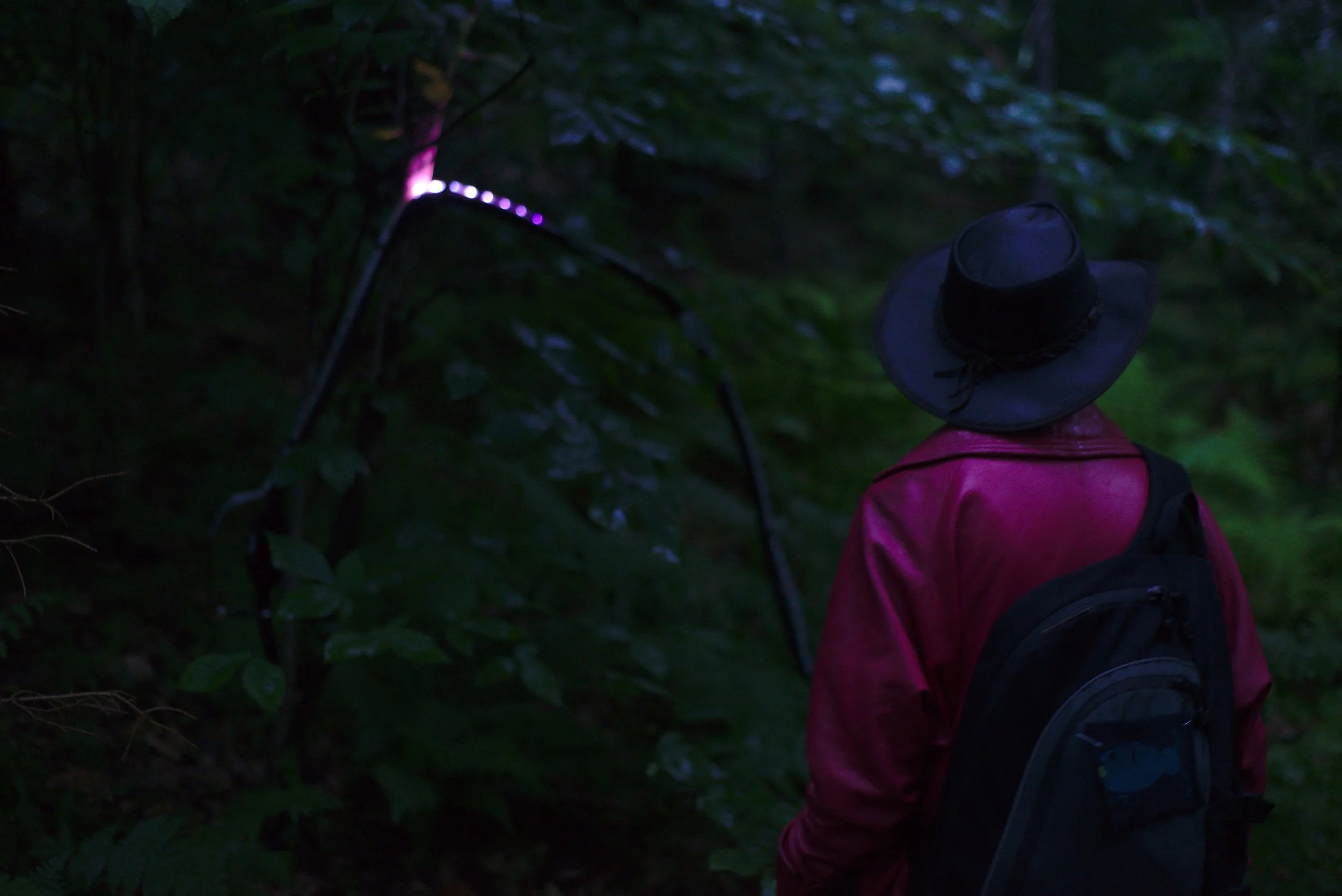


“I want a faerie light to lead me through the forest at night, off the trail and into a secret place.”
The Witch Lights incorporate a 55-meter-long, weatherproof installation with motion sensors and 1350 NeoPixel programmable LEDs, in order to achieve that vision.
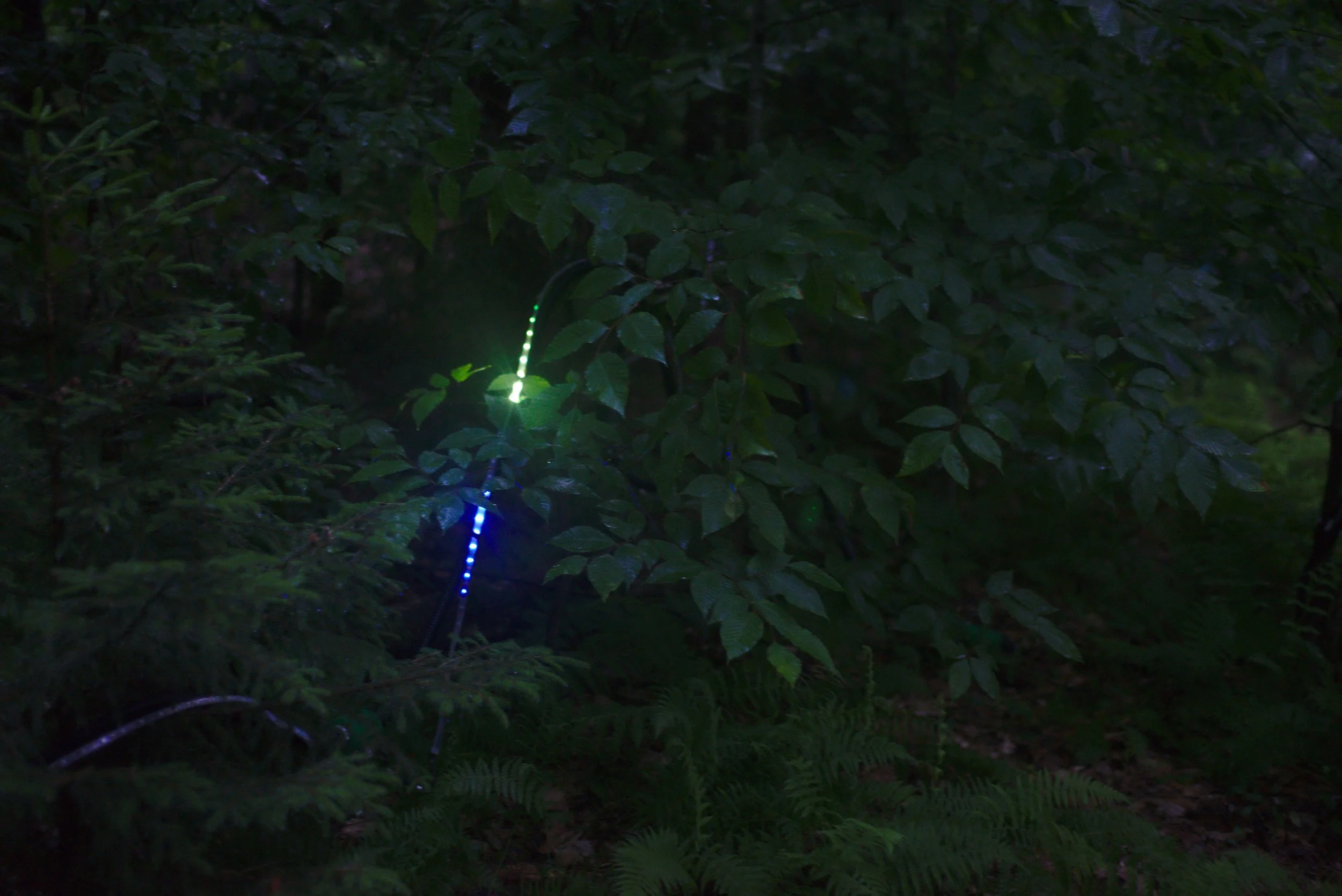
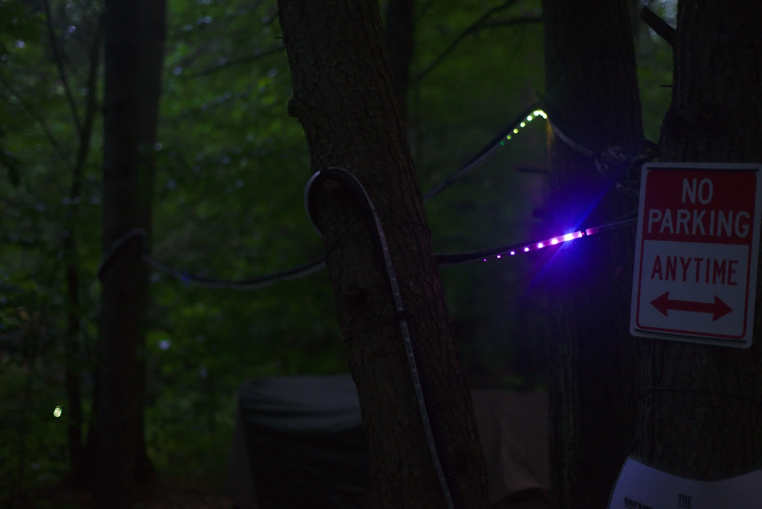
The lights race along their paths in both directions, leaving fading trails of different colors on their way.
"Witch Lights" is an old Scottish phrase for ghostly lights in the night time.
People who experienced the lights said they felt like something magical was leading them home. That the lights felt alive.
I was inspired by an art project I had seen the previous summer using motion sensors and lights, and knew that I wanted to create some kind of magical light effect that would react to people passing by, but what exactly was up in the air.
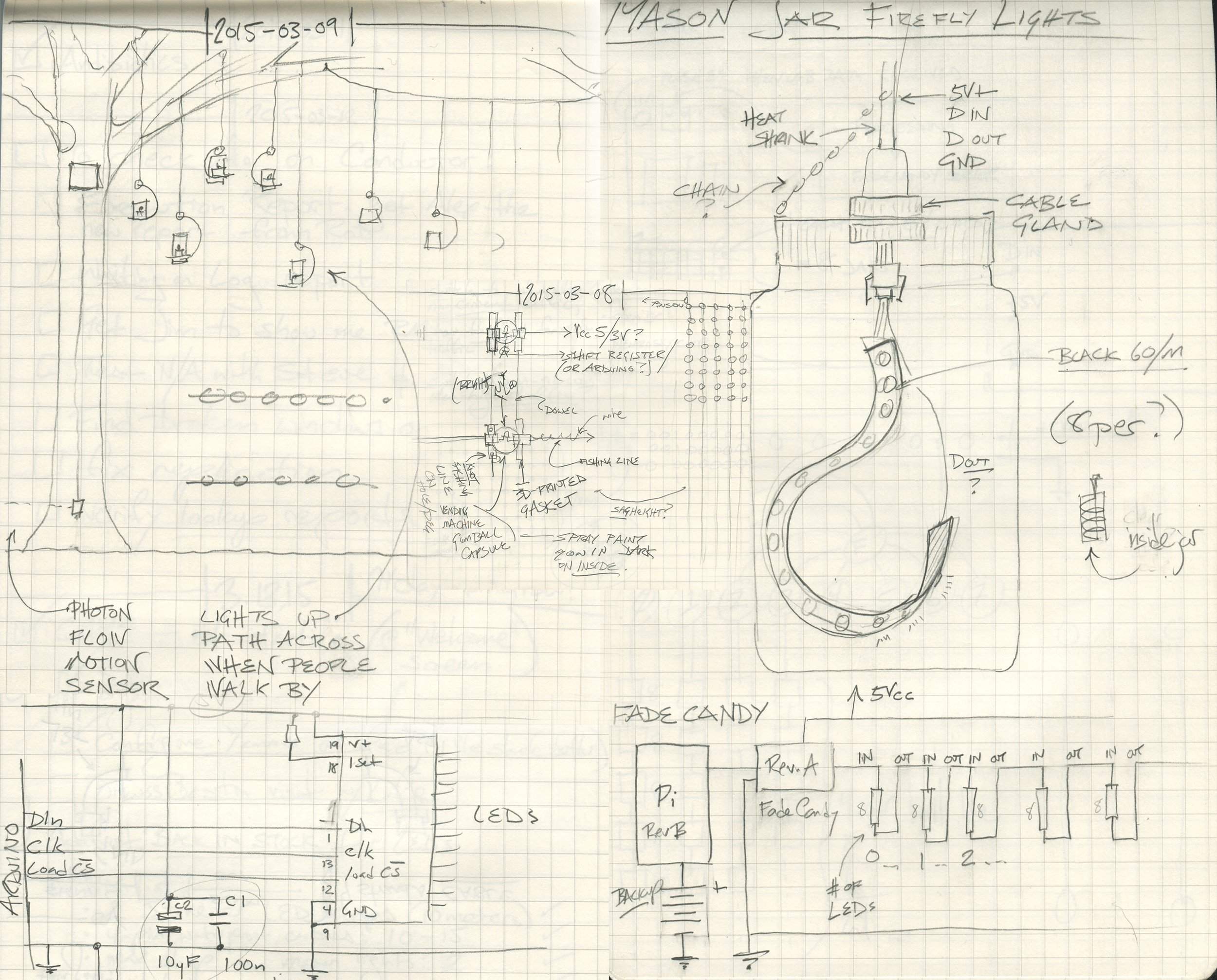
Hanging candle lights, mason jars with programmable LEDs, and matrices of ultraviolet LEDs in a grid that would fire off in sequences to create faerie lights were all explored.
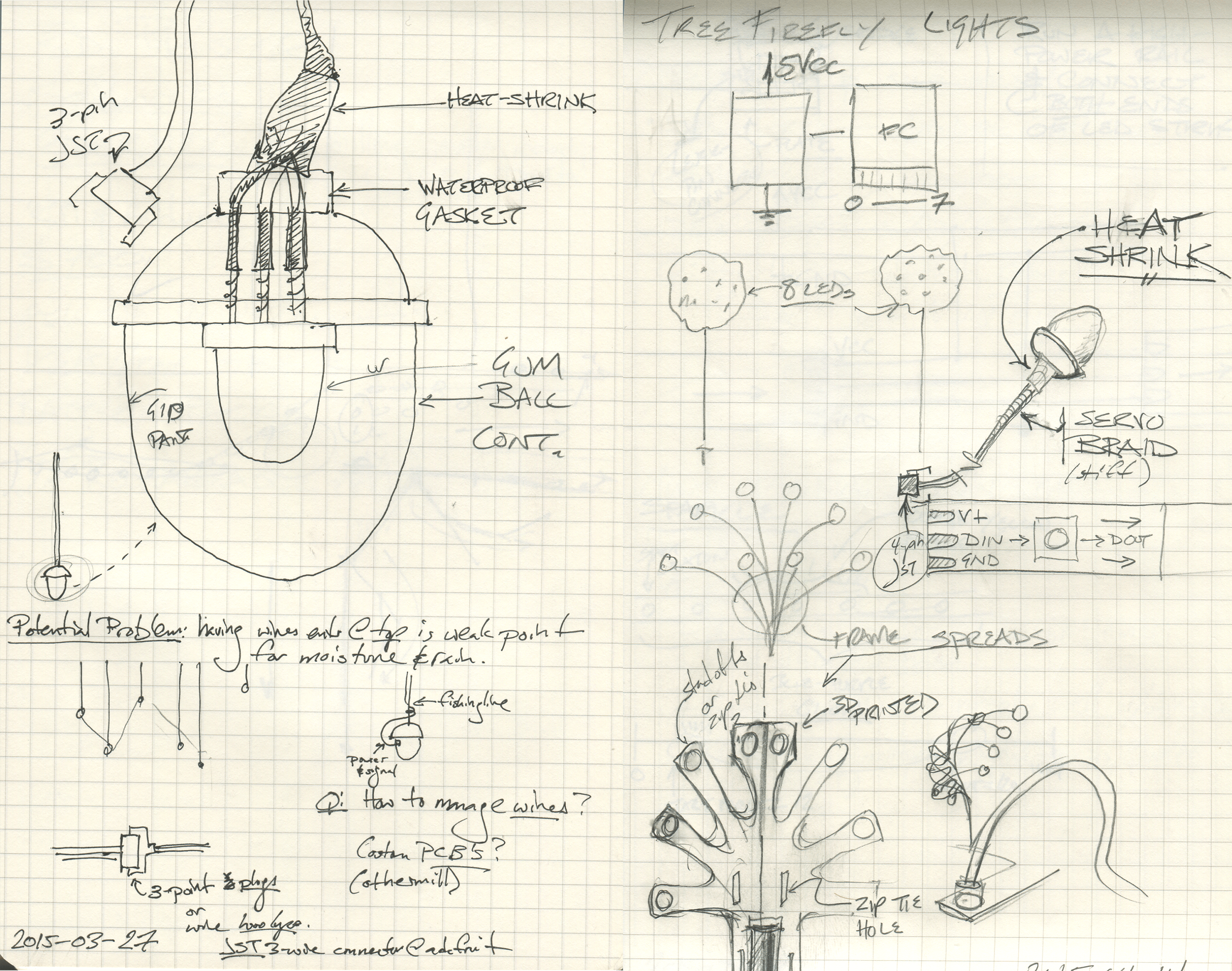
Following are selections from my notebook as I ideated possible directions.
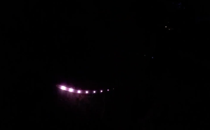
One idea that I ended up mocking up, but later abandoning, was to put bright UV LEDs into gumball capsules, which were spray-painted with UV-reactive glow in the dark paint. If you flashed the LED on for a split second, then off, the capsule would softly glow, then fade away. A trail of these would have created an interesting effect, with a bright light speeding away, followed by a fading trail of luminescence.
UV LEDs are not programmable, however, and the effort involved to assemble and control a chain of any length would have been prohibitively difficult and failure-prone.
I did sketch ideas for hanging the capsule LEDs in trees and bushes to flicker on and off with a firefly-like effect, and may return to that at some point.
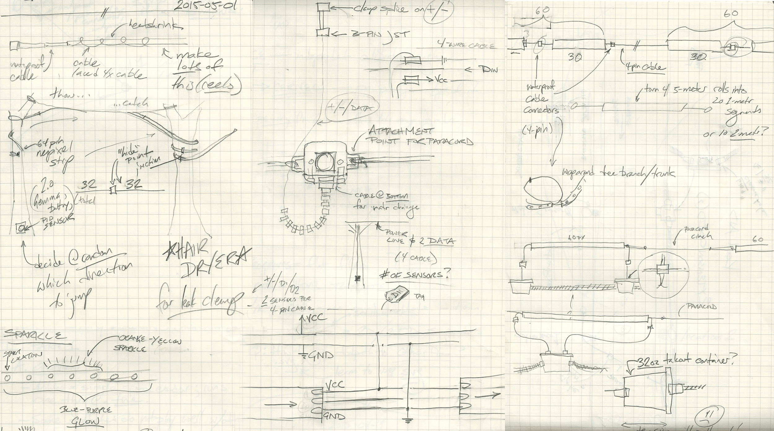
Once I settled on the idea of a will-o-the-wisp running along a long strip of NeoPixel programmable LEDs, I began work on tackling the different engineering problems posed by installing, powering, and protecting the lights in the woods.
Where would the sensors be placed? How to keep them from shorting out in the rain? How do I get the sensor signal from each sensor back to the control unit?
NeoPixel strips need to be connected to ground and power at each end. I knew I was going to end up chaining multiple strips together. How do I get power all the way down the length of the installation? How would the NeoPixels connect to the power line? How would the control signal be transmitted? How do I protect the power line and ensure that a short circuit doesn't cause a fire?
Above is a selection from my notebook at the time as I explored the problem. Since I was thinking of each problem separately, I was sketching different components to house the motion sensors, the power loom, and the NeoPixel strips. I started making plans to use heavy polypropylene take-out food containers to act as wire junction boxes to connect all these different components.
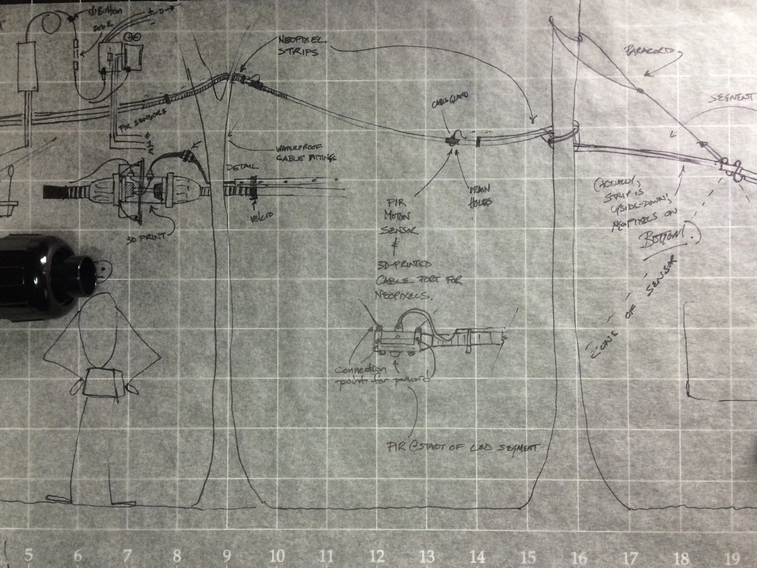
But when I mistakenly ordered a much larger gauge of conduit than I intended (in my defense, it was 2 in the morning), the form of the conduit screw-on fittings inspired me to sketch out a unified cable harness using 3D-printed junction boxes, which would also house the sensors. Resulting concept sketch shown below.
Above: unified harness concept sketch.
Below: finalized harness installation, for comparison.
Now that the rough form of the installation was set, I turned to developing the electronics and 3D-printed hardware required.
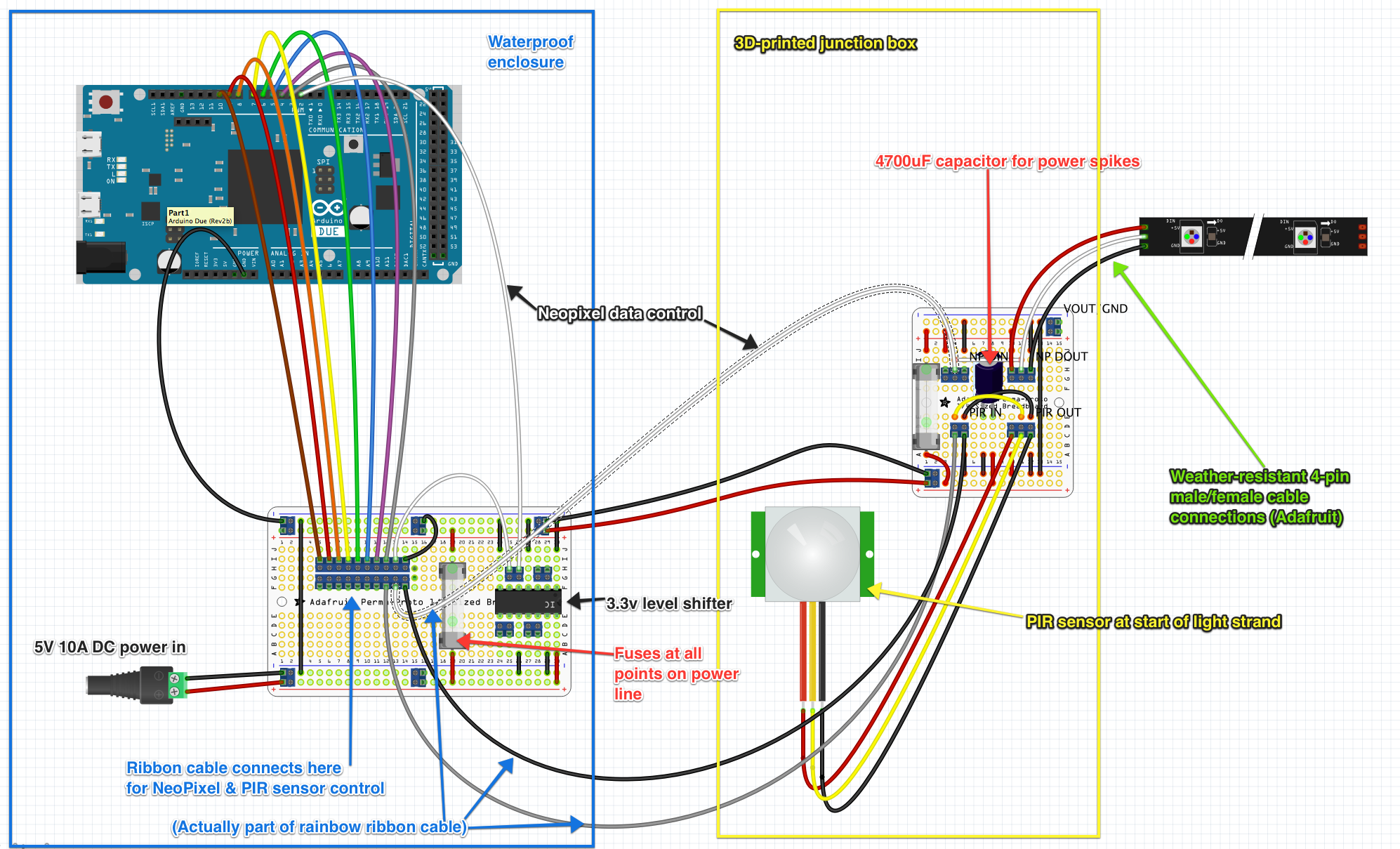
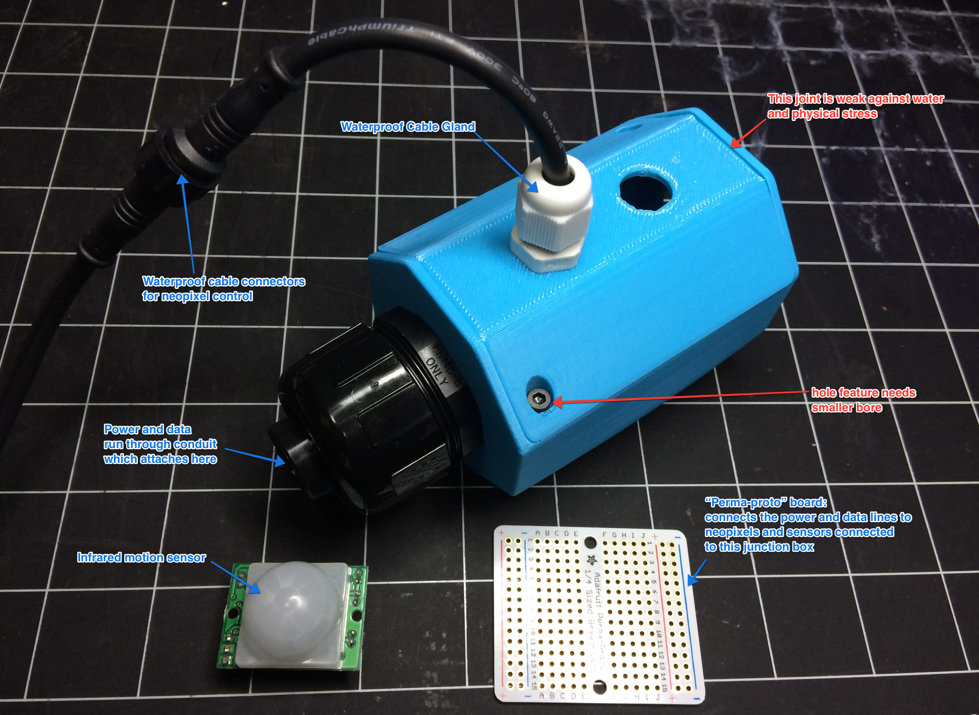
Since one design principle I firmly believed in was that this installation should be repairable on-site with a small tool kit, I designed circuit boards for each junction box that used standard screw terminals to connect the power, ground, NeoPixel data, and motion sensor lines. I sketched the whole thing out in Fritzing (one mid-development sketch from which is shown below).
I was able to download Solidworks models of the conduit fittings I was using, and designed the housings around them, and also around the geometry of the circuit boards I was using, the PIR motion sensors, and the waterproof cable glands used for the NeoPixel power and control cables.
Since I have extensive experience designing for my MakerBot Replicator (first generation) 3D printer, I designed the housings with rapid, reliable printing in mind. At each stage of the design, I made a test print. Then I refined the design based on what I learned from the test, and printed again.
With print times of a few hours and very few print failures, I was able to iterate my way to a final design very rapidly, with a minimum of wasted effort.
While I developed the housings, I also sketched out other details, such as how the NeoPixel strips would connect their power, ground, and data lines to the terminal boards in the housings.
I settled on a design using these 4-pin waterproof polarized cable sets, which would be soldered to the NeoPixel wires, with heat-shrink tubing protecting the delicate wiring.
This had an additional advantage: NeoPixel strips have to be connected in a specific polarized direction to work. By using these polarized cables, I could apply the principle of poka-yoke and ensure that there was no way to connect the NeoPixel strips to the harness incorrectly.
Once I signed off on the final housing design, I had to produce enough housings and circuit boards to assemble the full harness.
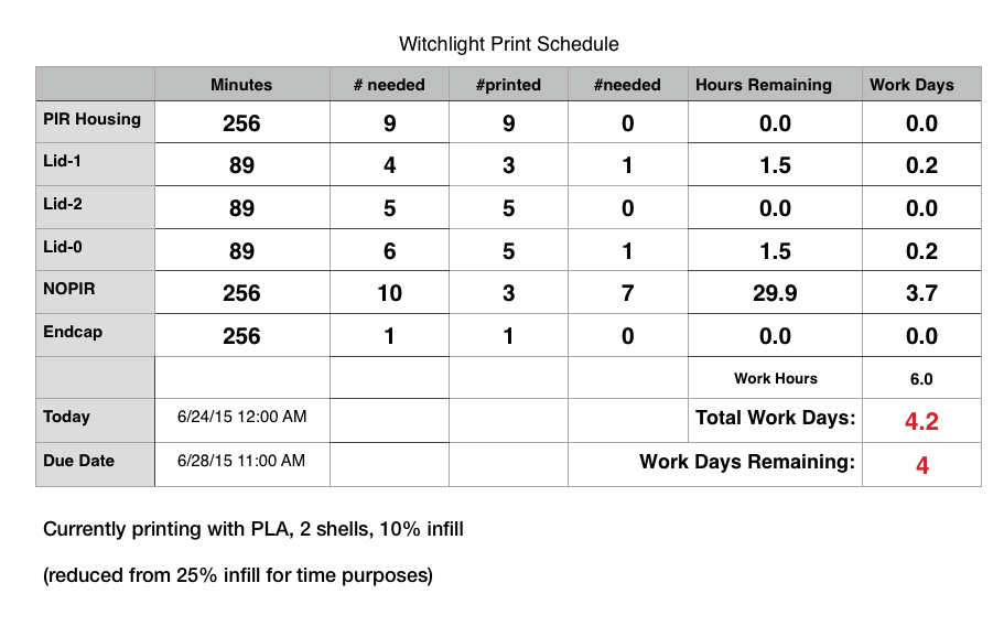
The trouble with 3D printing is, there's no economies of scale for production. Manufacturing time scales linearly with your quantity required.
I quickly determined how many of each configuration I needed, timed how long each component took to print, and put together a spreadsheet (below) to calculate out my production requirements.
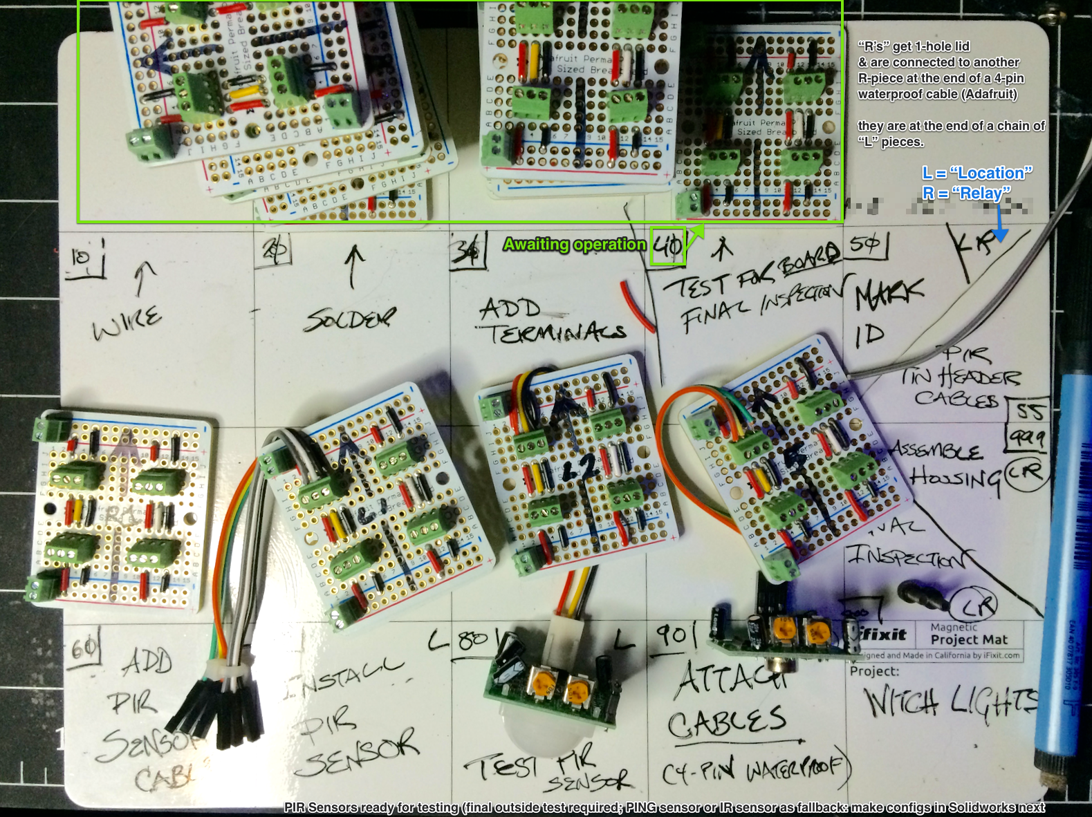
To manage constructing the circuit boards, I adopted a cross between a Kanban and a shop traveler to control the process. This made sure none of the boards made it into production without having gone through quality control checks.
The Witch Lights are 25 meters long each (approximately 145 feet total counting both sets), and have to operate in the rain and wet conditions. Data from motion sensors at the far ends of the chain have to run back to the Arduino microcontroller in the "brain" housing on the other end, and power from the battery circuit has to run the full length as well.
When assembling the harness, at each step, I took care to test for short circuits and for uninterrupted connectivity all the way back to the control housing. That's time consuming, but also hugely useful to catch possible wiring mistakes before they become real problems.
For the initial prototype of the Witch Lights, I worked feverishly to design, manufacture, test, and assemble the full 25 meter harness in time for the Firefly Art Festival in 2015. I barely slept for the two weeks leading up to the festival, and the morning of the day I was supposed to leave, I was still soldering and testing cables at 11:30 in the morning.
By 2pm, I had all of the components ready to go... they just needed to be assembled. And tested. And installed. And it was all going to have to happen on site. Because it was time to go.
So, I packed everything I could think of that might be necessary, somehow jammed it all into the back of a Mini Cooper, and drove the three hours up to Vermont. The next three days were spent feverishly assembling, testing, and installing a ten meter prototype of the lights, working on a tarp in the middle of camp.
But they worked.
Next up, I just had to extend the harness to full scale. What could possibly go wrong?
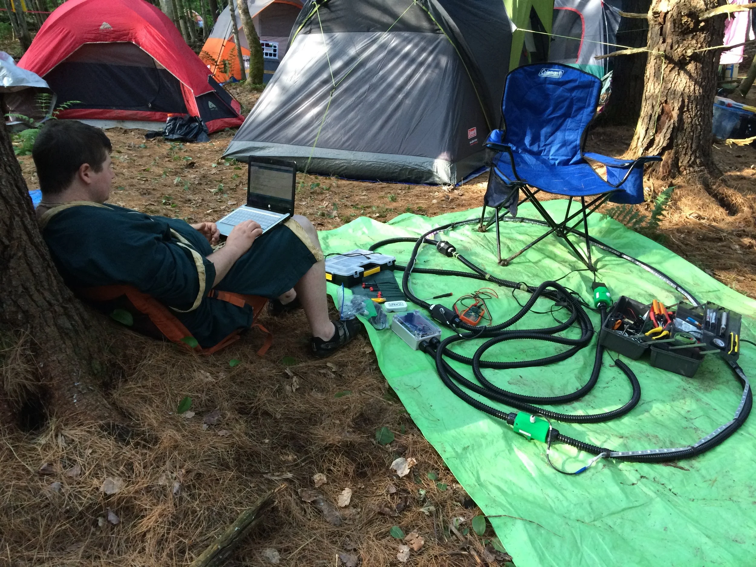
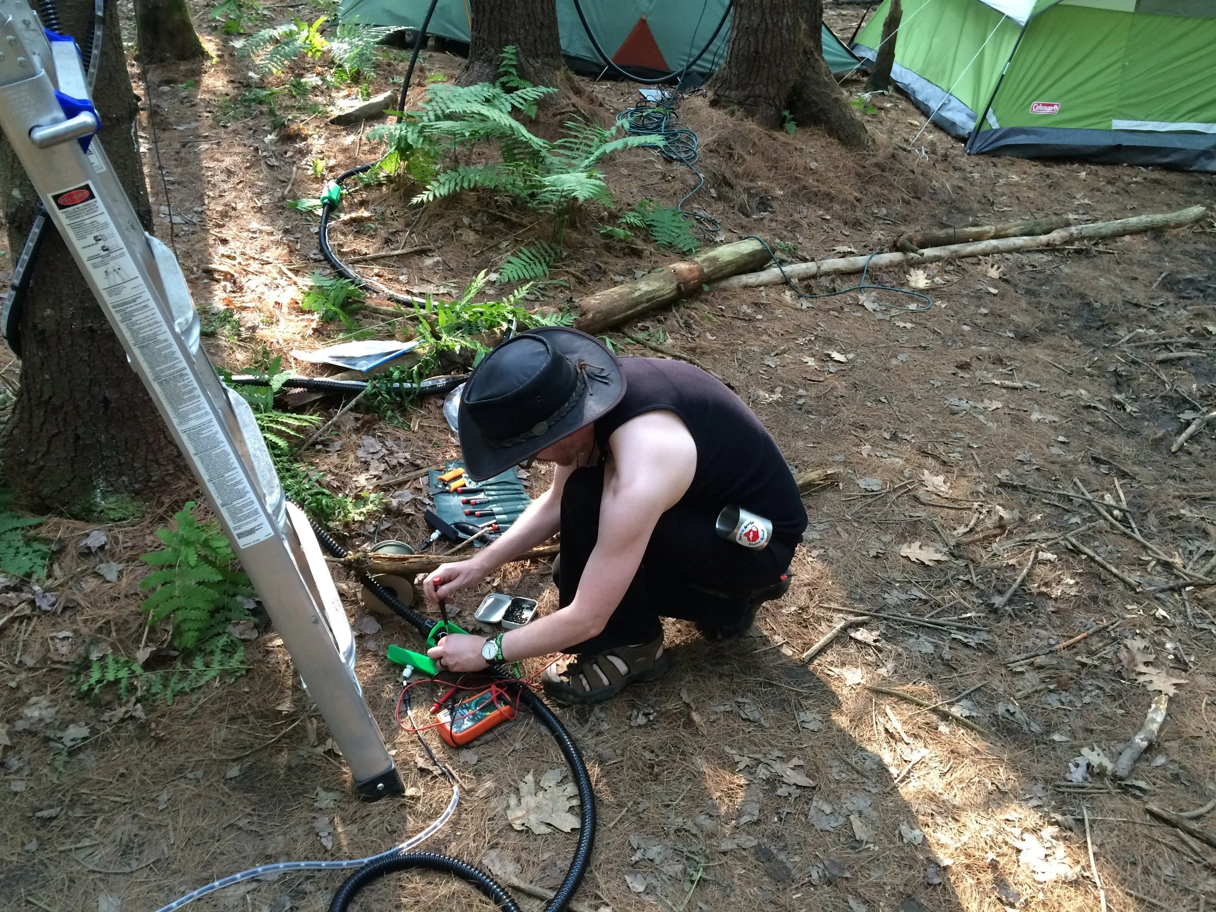
The Arduino brain of the Witch Lights is programmed using a hand-me-down linux netbook, because that's what I'm willing to risk bringing into the woods to be rained on.
Shown above is my friend Scott, who was reviewing my first draft amateur code, and helping me figure out how to make the animation accelerate in a lifelike manner. The conditions are pretty emblematic of what I had available to work with, which is why I was so adamant about the details of the wiring assembly design.
It turns out, when you build a wiring harness that's 25 meters long? Resistance becomes an issue. Also, as it turns out, that problem can crop up in ways that are not immediately obvious.
In my initial prototype, I used too narrow a gauge of wire for the 5V and ground wires. That wasn't a problem for the initial ten-meter installation, but when I extended the harness to 25 meters? Problem. Specifically, the wire resistance was just enough that, when paired with the load of powering 750 NeoPixel LEDs, the infrared motion sensors didn't receive 5 volts on the power pin.
The result: one of the motion sensors would trigger constantly, causing the Witch Lights to animate in a loop from one direction over, and over, and over. Which seemed like a bad motion sensor. Except the problem persisted even after I replaced the sensor.
Eventually I figured it out. The solution? Take the entire harness completely apart, and re-wire the whole thing, segment by segment. And then reassemble it. And that fixed the problem, right?
Nope.
As it happens, even with full gauge power wiring, the load of the LEDs is just barely enough to starve the motion sensor on the far end of the harness. And, so, I had to track down and install motion sensors that could operate with 3 volts DC or over.
And these are the things you never think of when you go, "oh, hey, I'll make an LED installation that's just a really long chain of NeoPixel strips. What could go wrong?"
The wiring harness, disassembled for re-wiring.
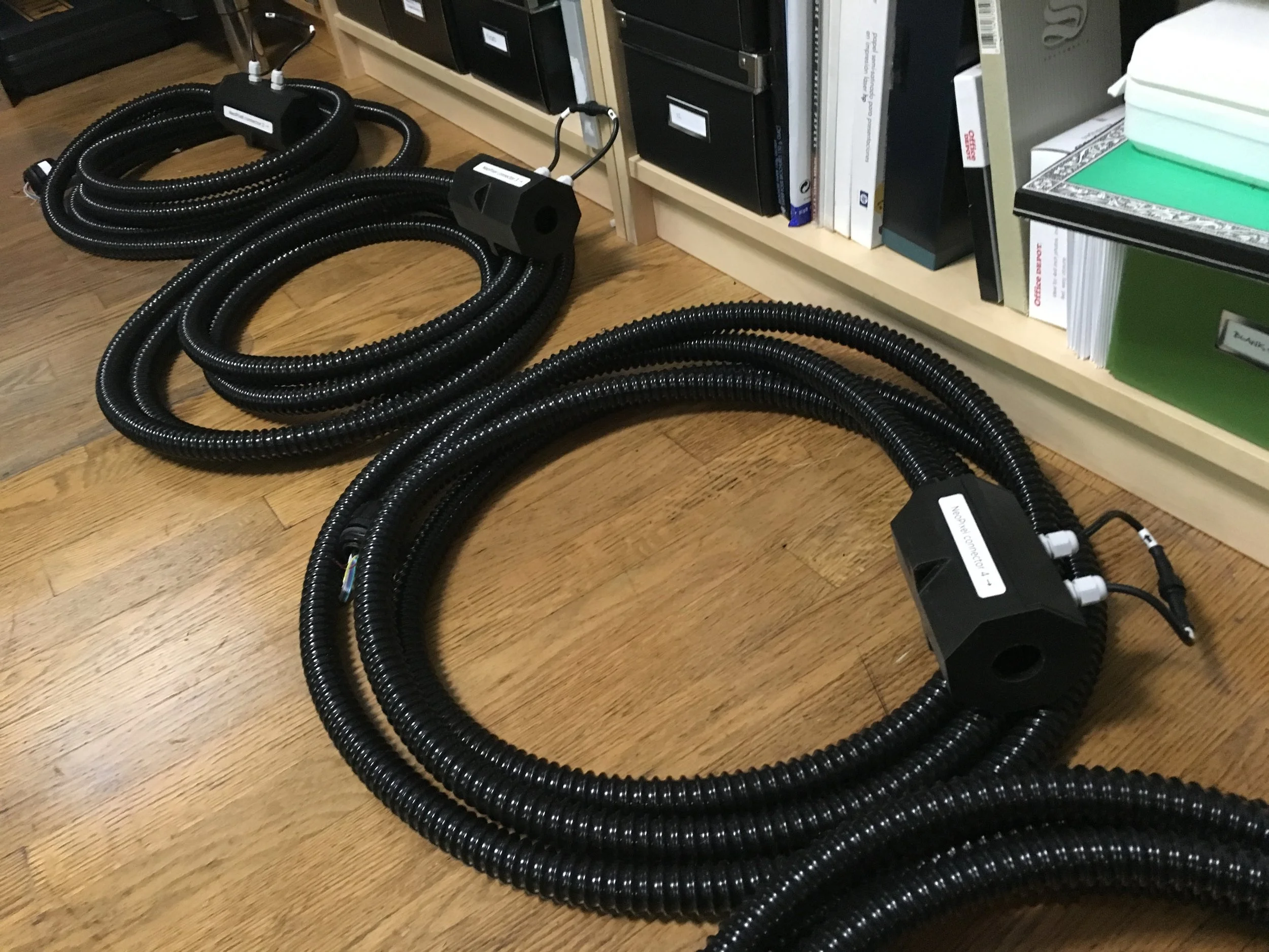
After assembling the first set of Witch Lights at full scale, I completely threw away and redesigned the 3D-printed housings from scratch, capitalizing on the lessons learned from 2 years of installing and running the Lights. The new housings are more waterproof, less prone to warping in heat, and stronger.
I used the new housings (shown above) to build a second set of the lights, for a total of two full scale wiring harnesses, totaling over 160 feet long.
The environment where the Witch Lights were installed posed one of the greatest challenges to overcome.
The installation and all of its tools have to be carried by hand approximately a half mile up a steep hill, across uneven terrain. There is no access to outside resources (not even a hardware store), so all necessary tools must also be brought along.
The hardware had to be designed so that it could be installed and repaired using a backpack toolkit, in the woods, using a flashlight, likely while sleep-deprived.
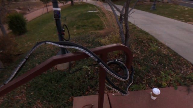
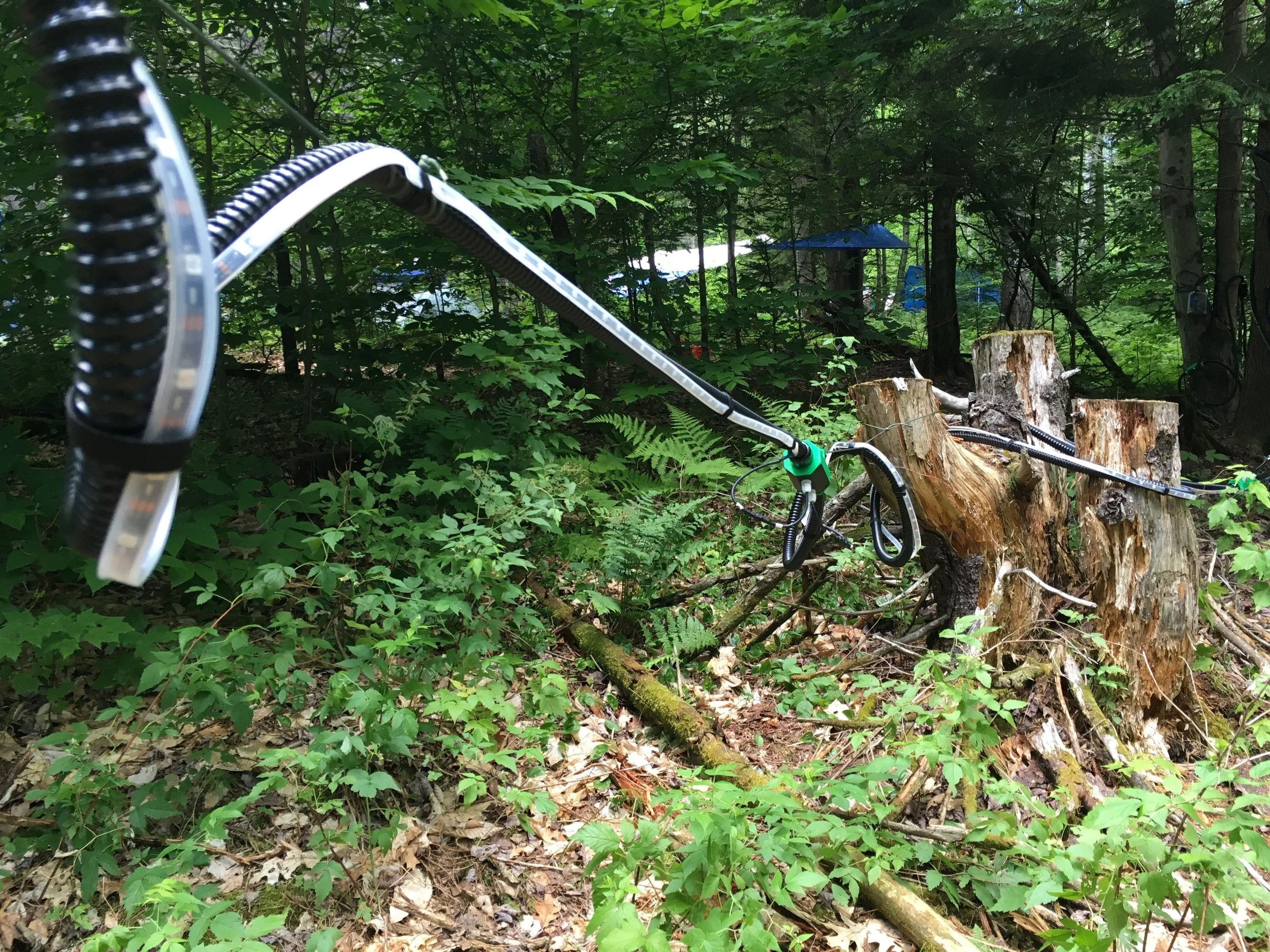
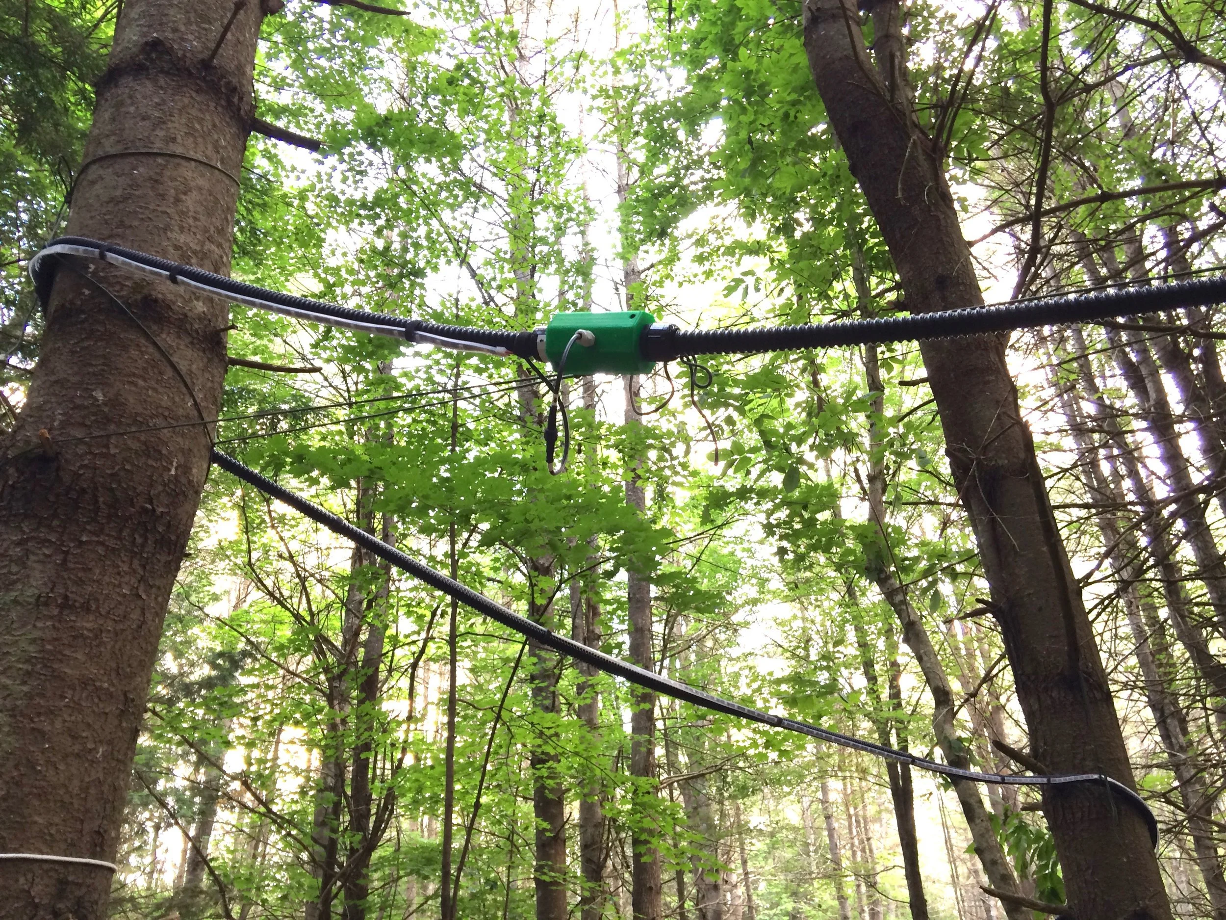
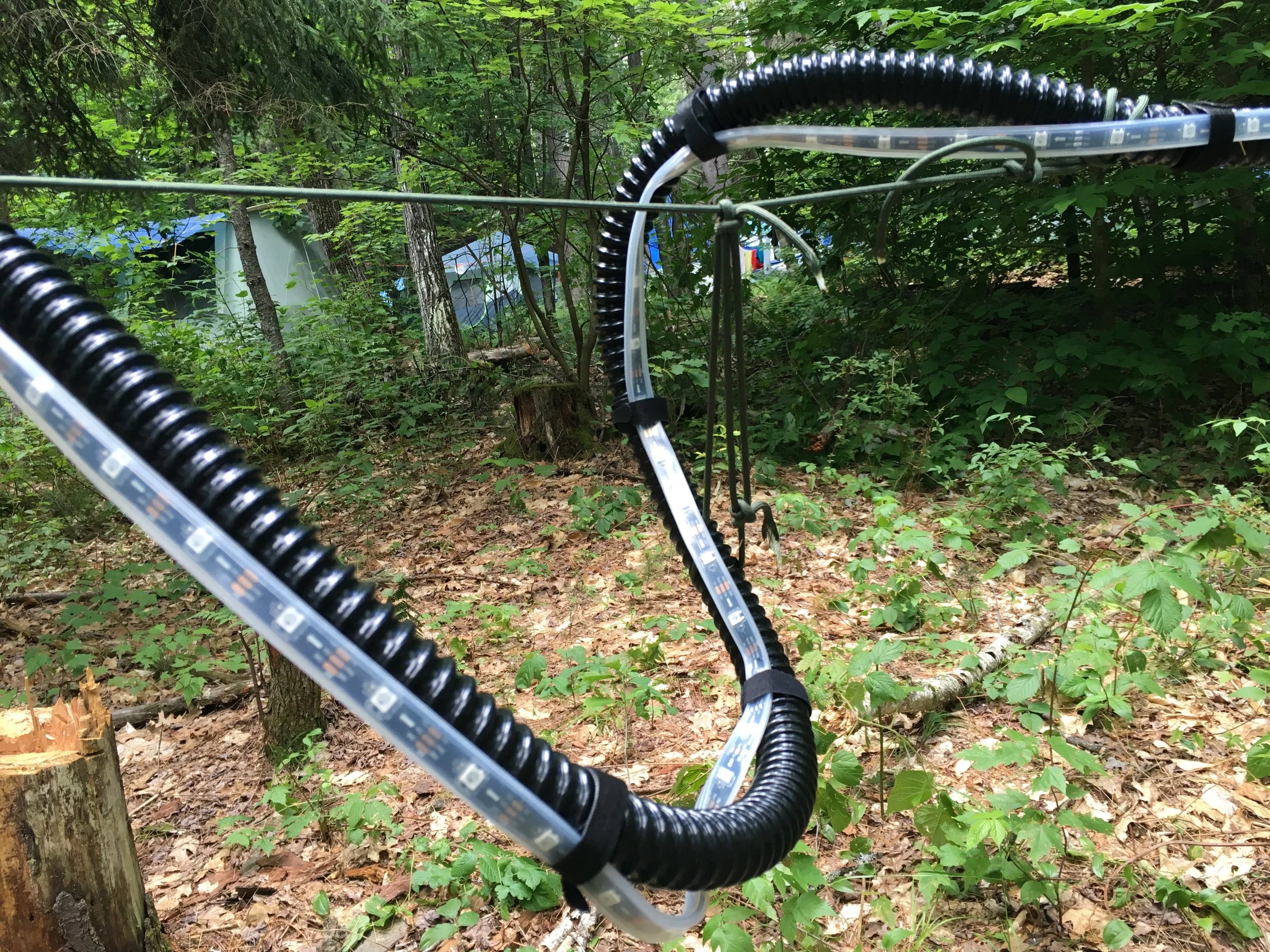
Below are daytime shots of installations from 2015 through 2017.
The lighter-colored grey line is one of the 9 NeoPixel programmable LED strips, which are controlled and powered by the data line and power harness running through the black flexible conduit tubing.
The green 3D-printed housing is one of the motion sensors.
The flexible conduit has enough structural strength that it allows the creation of mid-air loops like this one above.
Concept sketches and the first prototype deployment (below) had the lights positioned overhead.
As it turns out, people don't really look up. Especially in the woods, at night.
Later installations stayed at just over eye level, or lower.
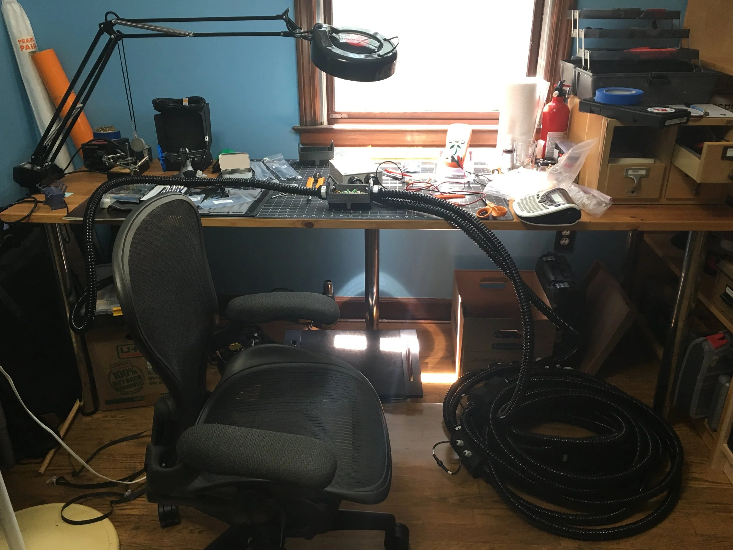
Taking an installation down generally takes about a half hour, with the assistance of a volunteer. The entire harness coils up for transport, and is easily carried out of the woods and stuffed into the back of a car.
Later, I prep the lights for storage by extending them back out to full length, testing them, disconnecting and stowing the NeoPixel strips, and coiling the harness back up and binding it in place with paracord.
The Witch Lights was a multi-disciplinary project, which required elements of: experience design; product development; CAD and 3D printing; electronics and sensors; Arduino and NeoPixel programming; small-run manufacturing processes and production management; and troubleshooting and problem-solving.
While I had some experience in all these areas, each of them required some uncomfortable growth in their turn, and the total of the project's demands were well beyond what I had conceived of when I decided to "do a fun art project with LEDs this summer".
Work continues on the animation code for the Arduino, and those who may be interested in contributing (or just curious) can find the current build on GitHub.
In addition to code, the GitHub site also contains 3D-printable files, a full bill of materials, and detailed documentation on electronics and assembly, with full instructions for construction.
If you are interested in contributing to the project, or have questions or comments, feel free to contact me.
This is a huge project, and many people helped out in large and small ways. Special thanks to:
And also thanks to Merlin, Avery, Scott, Abbey, Mike, and Scott for setup and breakdown help!